
How to build a diode voltage reduction adapter for your LiPo

Estimated reading time: 5 minutes
Portable ham radio operation require a portable energy source, e.g. a rechargeable battery. Usually lithium based batteries are chosen because they store a lot of energy while at very low weight. However, there are different types of lithium based batteries with varying cell voltage. For certain battery types a voltage reduction is necessary in order to prevent over voltage damage to your radio. This article shows how to build a simple diode voltage reduction adapter for reducing a 4 cell LiPo battery voltage to a level safe for consumption by the FT-817ND.
Table of Contents
Background
Usually I am supplying my FT-817ND radio with a 4 cell LiFePo battery during. It has a nominal voltage of 13.2 V which matches perfectly the FT-817ND’s recommended operating voltage of 13.8 V ± 15%. However, this battery only has a capacity of 3100 mAh. For the European SOTA Activity Day I found myself wanting a battery with a larger capacity in order to stay at the summit as long as possible. After a bit of research I purchased a Lithium based battery with a capacity of 5000 mAh. Although I had thought that I had purchased a LiFePo upon arrival of my order I had to recognise that I had bought a LiPo battery instead. A 4 cell LiPo battery has a output voltage of 16.8 V when fully charged. Unfortunately this is high enough to damage the FT-817ND.
Consequently I had to think of a way to reduce that voltage to a level safe for consumption by the FT-817ND (< 16 V). Many switched DC/DC converters have high RFI emissions which can overload the receiver. During a web research I came across the solution of using in series diodes for reducing excessive voltage.
Build a diode voltage reduction adapter
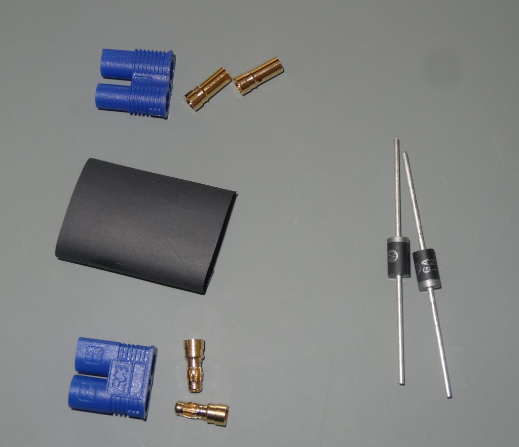
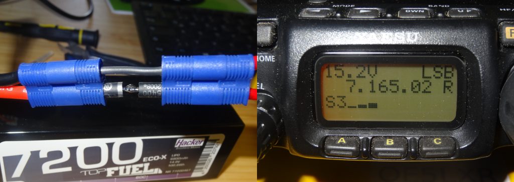
In order to get below the 16 V threshold the LiPo battery voltage needs to be reduced by at least 0.8 V. Hence at least two in series diodes are necessary. 1N5400G diodes have been used due to being at hand and fitting the required parameters. The 1N5400G has a forward voltage Vf = ~0.8 V and can handle a forward current up If = ~3 A. The FT-817ND consumes about 2 A upon transmit so we are on the safe side here. Below you can see all the required parts spread out in preparation of the build.
As a first step the cathode of D1 is connected with the + plug being plugged into the batteries VBAT line. Then the anode of D2 is connected with the + receptacle of the adapter leading to the radio.
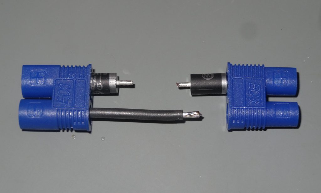
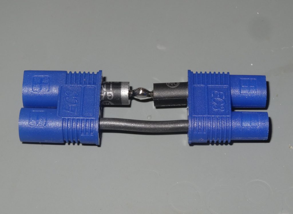
In a second step the D1 anode is connected with the D2 cathode. Furthermore the – plug is connected to the – receptacle with a solid wire.
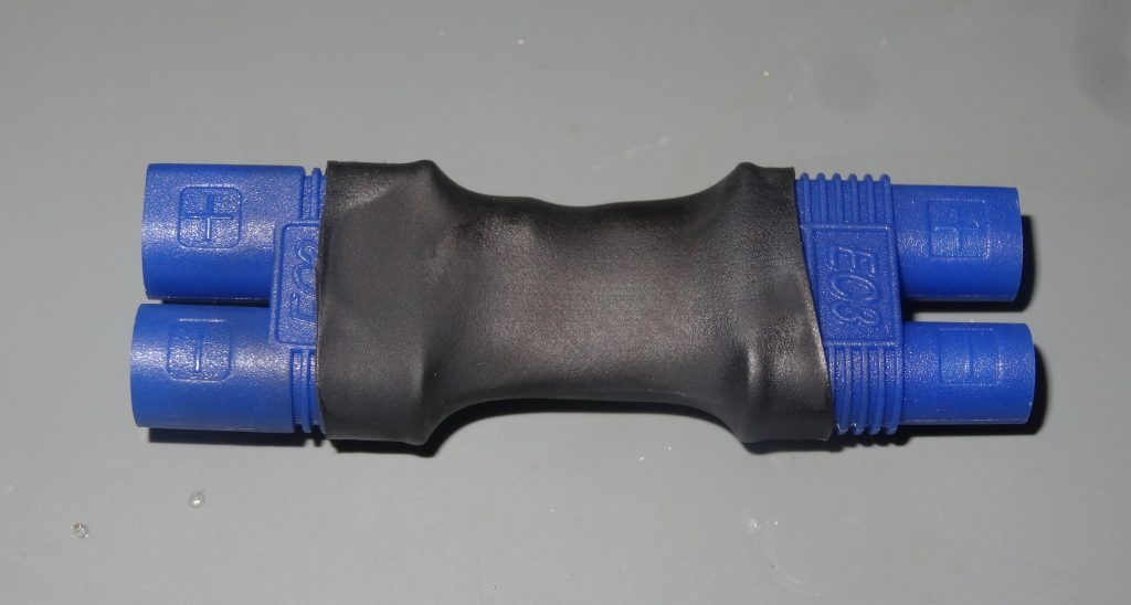
As a last step the diode voltage reduction adapter innards are covered in heat shrinking tube. Its purpose is to prevent the diodes from humidity and dirt during portable ham radio operation.
Upon hooking up the adapter between LiPo battery and FT-817ND the radio displays a battery voltage of 15.2 V. This is exactly 1.6 V (2 x 0.8 V) lower then the 16.8 V provided by the fully charged battery.
Since the battery voltage of the LiPo battery is dropping as its energy is depleted you should continuously keep an eye on it. Once the battery voltage drops to a level which allows safe radio operation without the adapter you can remove it.
4 comments
BH4FRX 10/01/2022
did you consider add a comparator and a relay before the diode array?
Alexander Entinger (OE5LXR) 10/01/2022
Dear OM Ke Ma (I hope I'm getting this right, I'm copying it over from QRZ), Great reading from you! I assume you suggest that by adding a comparator and a relay the diodes could be bypassed when the LiPo voltage drops below the critical level in order to save battery? This would be a great addition indeed. In my case I chose a simple solution because I can monitor the battery voltage on my radios display and manually remove the diodes when they are no longer needed. Since my focus is on portable operations (SOTA) I prefer to keep my setup as simple as possible, since every additional circuit introduces another possible point of failure - and you really don't want to lose a summit due to a malfunctioning power circuit ;) Anyways, that's just my philosophy! All the best, vy 73 de Alex, OE5LXR
Andrew 13/07/2022
I did similar, though with switches to bypass the diodes when the voltage drops. I used 4 diodes, with switches across each pair. I've had people tell me to use regulators, however with their regulators they suffered from noise. The diode method is simple and it works well. I've never used the switches on mine other than when I was testing. regards andrew vk2pez
Alexander Entinger (OE5LXR) 13/07/2022
Hi Andrew! Thank you for sharing your experience! I did not mention it in the article, but I once bought a DC/DC switching regulator which produced so much noise, that I nearly lost the activation of a SOTA summit. Since then I don't mind converting a bit of energy into heat, if it means a RFI clean energy supply. From your QRZ profile I'm seeing you are doing SOTA too - have you ever had to actually use those switches because voltage decreased too much during an activation? Cheers, vy 73 de Alex, OE5LXR