A cheap DIY dummy load using wire wound power resistors
TL;DR: If you read nothing else, at least make sure to never use wire wounder power resistors for a dummy load, due to their terrible RF performance.
During the winter holidays I did spend some time assembling ham radio kits, most notably the QRPMe Two Tiny Tunas which is a rock-bound QRP CW transmitter for 40 meters. Since I do not heavy ready access to shortwave antennas (= none) I wanted to try out the transmitter on a dummy load first. While I’ve got a big dummy load capable of dissipating up to 100 W of power it is at the same time sporting a UHF socket. Bummer, since all those QRPMe kits are utilizing the RCA connector known to most for usage in audio/video applications. Consequently the idea of building a cheap DIY dummy load leveraging a box of 100 Ω / 50 W wire wound resistors was born.
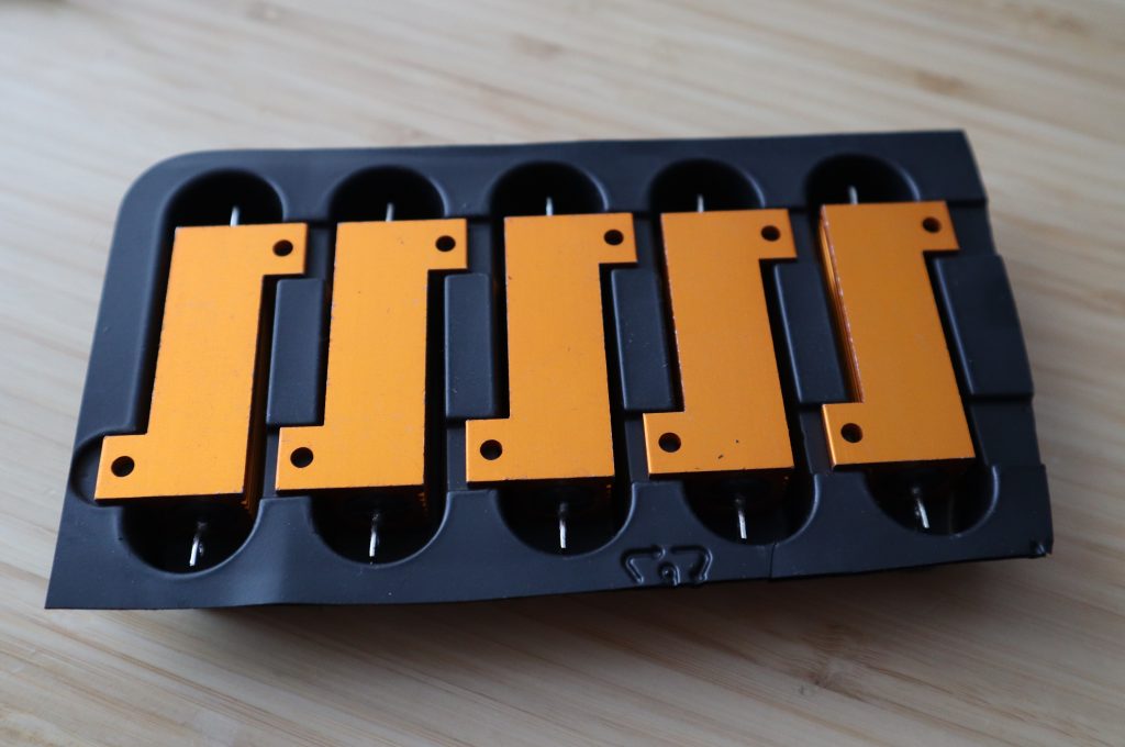
unaware of their impending fate as a dummy load.
My plan was to connect to of those 100 Ω resistors in parallel in order to obtained the desired 50 Ω expected from my tiny QRP CW transmitter.
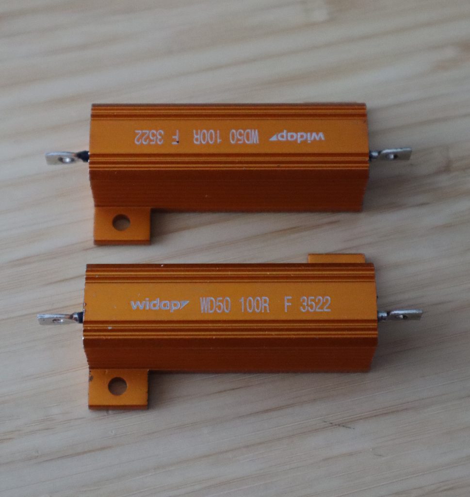
maybe not so blissfully unaware of their
impending dummy load fate anymore.
The first order of business was to stack them using M3 spaces and screws.
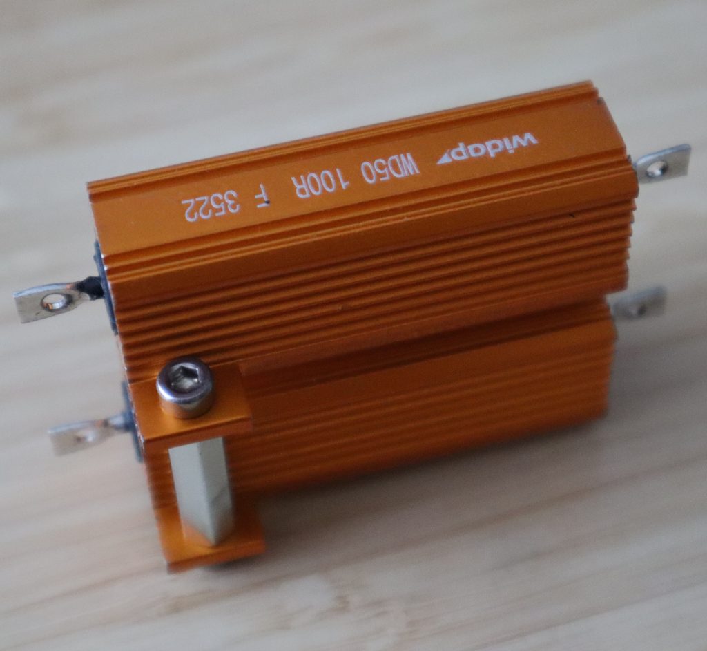
resistors, suspecting their impending dummy load fate.
Second order of business was to connect both resistors in parallel and attach a RCA plug.
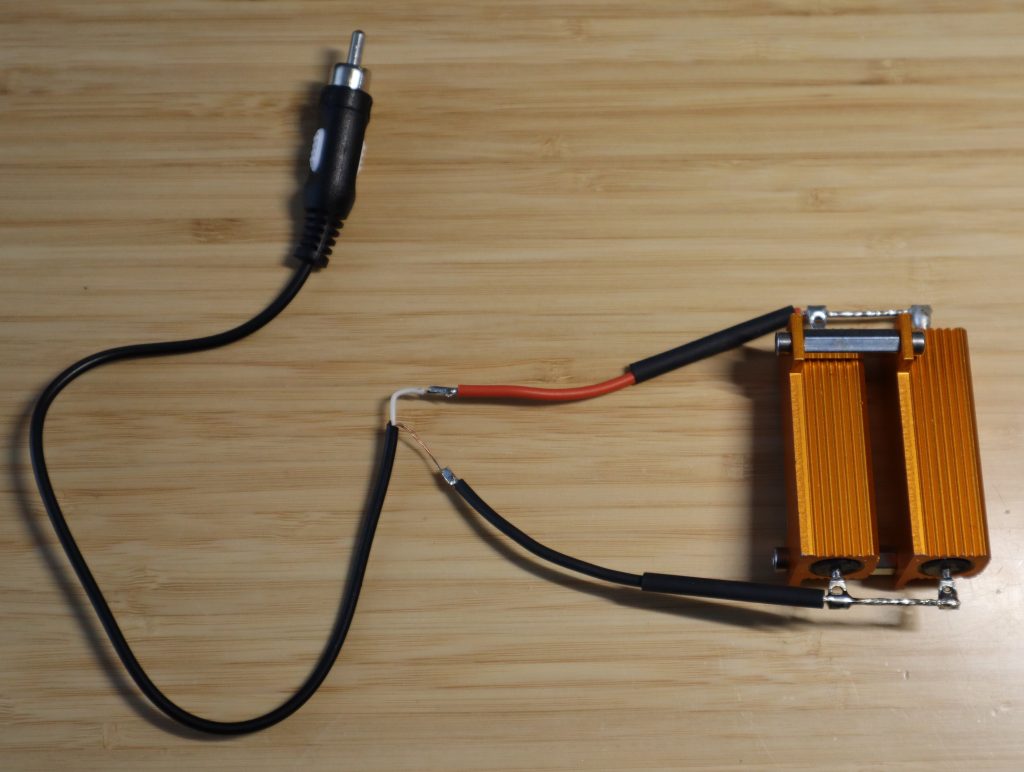
wound resistors and a RCA connector.
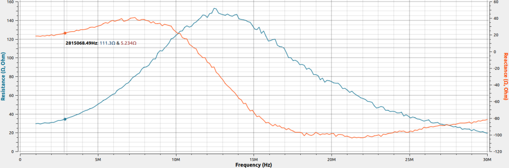
Now before I connect this little contraption to dissipate the transmit power of my newly assembled QRPMe Two Tinned Tunas transmitter I’d like to get a little clarity what’s the behavior of this dummy load over the relevant frequency range. So let’s bring out any network analyzer my PocketVNA.
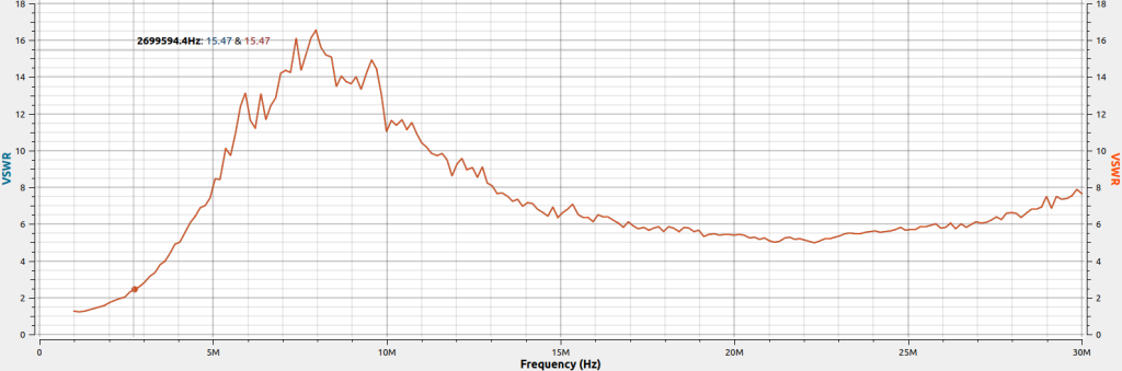
VSWR(7MHz) ~ 4
Using the VNA I found that my wire wound 50 Ω dummy load contraption was anything but a perfect impedance match. In fact at the desired target frequency of 7 MHz (the transmit frequency of my rock-bound Two Tinned Tunas transmitter) the measured VWSR was a whopping factor of 4! Printing Re{Z} and Im{Z} quickly solved the problem showing that the wire wound dummy load had a high reactance behaving like an inductor at lower frequencies and like a capacitor at the higher frequencies.